The Electrical Experimenter - January
1917
RadioĀ DetectorĀ Development byĀ H.Ā
WinfieldĀ Secor,Ā A.I.R.E. While wireless telegraphy is a far cry from the
philosophy and traditions of the Hindoos, it may not be inopportune to cite, for purposes
of comparison, an ancient tradition of the Hindoo priests which brings out in a marked and
comprehensible manner the gigantic loss existing in wireless telegraphic transmission,
with especial regard to the infinitesimal amount of energy that is received at the
wireless receiving station with which to actuate the detector.
The Hindoos, with all their profound philosophical deductions, were
never able to figure out the age of the earth any more definitely than our geologists and
scientists have to-day. But they did have a very good example by which to live a practical
idea as to this vast stretch of time. Said they:
Let us suppose that we have a marble cube 1 mile high x
1 mile wide and 1 mile long. Suppose, also, that a lady wearing a shawl visits this marble
cube once in every hundred years (presumably not the same lady), and that she brushes the
marble once with her shawl. In time, of course, the marble will be worn down to the size
of a pea, and he who can figure out the length of time in years required for this to be
accomplisht, would know the age of the earth. And the Hindoos called this period of time
one Marcalper, and the actual age of our planet as one Marcalper times one Marcalper.
This is a homely little story which may help by comparison to instil in
the lay mind something of the enormous loss of energy which takes place in the
transmission of Radio signals over great distances.
We will not deal exhaustively, or even attempt to, in the present
discussion, on the efficiency of wireless transmission for any given condition or set of
conditions, but an example of the amount of energy utilized at a typical trans-oceanic or
trans-continental radio station and that arriving at the receiving station may be
illuminating.
We may easily assume that the amount of power radiated at a
transmitting station for a 3,000 or 4,000 mile range is 50 K.W. or 50,000 watts. Bearing
in mind that a watt is equal to 1 volt times 1 ampere, and that it is considered excellent
when 20 micro-amperes or about .01 micro-watt is registered at the receiving station with
which to actuate the detector, then we have some idea as to how all-important the radio
detector is and we have an analogy to a degree, with the Hindoo philosophy cited above.
With 50 K.W. used at the radio transmitter and but .01 microwatt received, we find that
this is but one five-trillionth (l/5,000,000,000,000th) of the energy sent out.
Before leaving this point it is well to mention that 10 micro-amperes (1 micro-ampere is
equal to one one-mi1lionth of an ampere), is considered a weak signal and 20 micro-amperes
received current a strong signal. Technically speaking, radio detectors are usually rated
by the amount of electrical energy in ergs necessary to actuate them.
Ā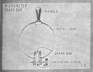
One of the first, and, so far as we know, really the first wireless detector which would
manifest and interpret the electro-magnetic waves sent thru the ether by a spark discharge
such as that from a static machine or induction coil, is the Hertz Micrometer Spark Gap
or Resonator, shown at Fig. 1.
This comprised simply an insulated handle on which was mounted a
flexible metal loop and the abutting ends of which carried spark points or balls, which
could be separated or brought very close together by a fine micrometer screw attachment as
shown. For short distances such as in laboratory tests over a few hundred feet, the spark
gap resonator proved successful and showed Heinrich Hertz the way to his important
deductions on which is based to a very large extent the wireless telegraph that we know
today. The gap is regulated when in use until tiny sparks are seen to pass between the
points every time the transmitting key is deprest.
Ā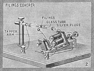
Next we come to the Filings Coherer as used by Guglielmo Marconi in the first
commercial radio sets which he built and installed on a number of vessels. The coherer is
shown at Fig. 2 with its magnetic tapper, resembling a vibrating type electric bell,
which, having its circuit closed by the relay connected with the coherer, served to shake
the glass coherer tube and the metal filings within it and to decohere the filings or
shake them apart. The coherer was then ready for the next signal.
The metal filings of certain and exact proportions as found by lengthy
experiments (after the method of Professor E. Branly of France) are placed within the
evacuated glass tube as shown. This is carried on an ivory rod. Normally, and before the
arrival of a wireless impulse from the transmitting station, the filings lie loosely in
the tube and the resistance of the coherer is very high, causing the relay to remain
neutral. When a wireless signal arrives, the current induced in the antenna passes thru
the coherer to earth and causes the minute metal filings (usually a mixture of nickel and
silver) to "cohere" or stick together. This has the effect of lowering the
resistance of the coherer quite markedly and permits sufficient battery current to pass
thru it and thus close the relay armature.
Simultaneously the decoherer or tapper circuit is closed and in the
final radio receiving sets of this type developed by Marconi a Morse tape recorder was
also connected in the circuit, upon which the incoming dots and dashes were recorded and
the operator could then decipher them at leisure. Moreover, there was a permanent record
of every message received in this case, which is often of paramount importance, especially
in military and naval work. The coherer, however, had several defects in that it was not
very sensitive and was difficult to adjust. It often lost its adjustment, in many
instances, a minute or two after it had been regulated or set.
Ā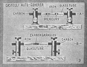
Referring to Fig. 3, we have what is known as the Auto-Coherer. Several types of
this detector have been evolved, but are practically extinct nowadays, owing to lack of
sensitivity and other untoward features. One of the principal auto coherers developed was
that known as the Castelli coherer and is said to have been used at one time by the
Italian navy. It employed one or more globules of mercury within a glass tube, this
globule (of 1.5 to 3 m.m. diameter) being placed between iron and (polisht surface) carbon
electrodes, preferably, as shown in the illustration. A modification of this arrangement,
first used by Mr. H. Gernsback, involved the substitution of polisht carbon granules
between an iron and carbon electrode. These detectors were used with a telephone receiver
and battery (one dry cell). They possess the faculty of establishing decoherence
automatically, and thus are always ready to receive the next signal upon the cessation of
the previous one. Their resistance falls upon receipt of a signal.
Ā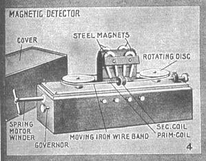
The detector illustrated at Fig. 4 is the well-known Rutherford-Marconi Magnetic
Detector. This instrument operates on a very unique principle, viz., that of the
reduction in any hysteresis effect occurring in an iron core, when this core is subjected
to the effect of a Hertzian wave current passing thru the receiving circuit, according to
the researches of C. Maurain. The complete detector is so arranged that a band of fine
insulated iron wires constantly revolve about two rotary drums, driven by a spring or
electric motor, and a pronounced hysteresis or magnetic frictional effect is produced in
that section of the traveling iron wire band directly under the poles of a set of steel
magnets mounted as shown. At this point there is also placed a small transformer
containing a primary and secondary coil. Thru the primary coil is past the aerial current
induced by the incoming electro-magnetic wave, while to the secondary coil is connected a
pair of low resistance telephone receivers. ĀĀĀĀ
It is evident, from the foregoing explanation, that at every incoming
signal there will be a sound heard in the 'phones as the Hertzian wave currents flowing
around the primary coil cause partial cessations or reductions in the hysteresis effect
produced in the moving iron wire band.
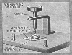 The Peroxid
of Lead detector devised by S. G. Brown of England is illustrated at Fig. 5. This
detector has proven quite successful and is used with a pair of sensitive telephone
receivers and a critically adjusted battery current. The instrument comprises a peroxid of
lead pellet mounted between an upper lead disk and a lower platinum one; the
pressure on the peroxid of lead pellet being adjustable by means of a thumb screw and
spring in the usual fashion. This detector has been termed, more or less correctly, the dry
electrolytic detector and its action is supposed to depend upon the fact that an incoming
oscillation intensifies the counter-electromotive force set up by the cell
(electro-chemical action due to lead-peroxid lead-platinum couple) and which opposes the
applied battery current (1.5 volts about), thus causing the detector to increase its
effective resistance. This results in a drop of current in the 'phone circuit; as soon as
the oscillation ceases the 'phone current increases. The Peroxid
of Lead detector devised by S. G. Brown of England is illustrated at Fig. 5. This
detector has proven quite successful and is used with a pair of sensitive telephone
receivers and a critically adjusted battery current. The instrument comprises a peroxid of
lead pellet mounted between an upper lead disk and a lower platinum one; the
pressure on the peroxid of lead pellet being adjustable by means of a thumb screw and
spring in the usual fashion. This detector has been termed, more or less correctly, the dry
electrolytic detector and its action is supposed to depend upon the fact that an incoming
oscillation intensifies the counter-electromotive force set up by the cell
(electro-chemical action due to lead-peroxid lead-platinum couple) and which opposes the
applied battery current (1.5 volts about), thus causing the detector to increase its
effective resistance. This results in a drop of current in the 'phone circuit; as soon as
the oscillation ceases the 'phone current increases.
Ā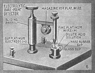
The Bare-Point Electrolytic Detector illustrated at Fig. 6 has been the subject of
much discussion among radio men as to who really was the basic inventor of it. But most
writers of the day give credit, jointly, to Dr. Michael I. Pupin (1899), Professor
Reginald A. Fessenden (1903) and W. Schloemilch (1903).
The action of this detector is based upon the fact that if an extremely
fine platinum wire, measuring a few ten-thousandths of an inch in diameter is allowed to
partially immerse its extremity in an acid solution (such as one composed of five parts
water and one part nitric acid) that an incoming Hertzian wave current will tend to arrest
the strong polarization (the production of fine gas bubbles) set up about the fine
platinum wire, which is usually made the anode in the battery circuit. Further, the
electrolytic detector has been found by Professor G. W. Pierce to act as a rectifier and
that the inherent action is also based on polarization capacity at the electrodes as first
described by Pupin in 1899. Dr. L. W. Austin and others have found that the fine platinum
wire may be positive or negative for feeble oscillations with equal results. The acid
solution is contained in a glass or carbon or zinc cup as shown, and this acts as the
cathode in the battery circuit. This detector possesses the function of acting as its own
battery when a carbon or zinc cup is used, as this forms a miniature cell--carbon (or
zinc) acid, platinum. This inherent battery action was intensified considerably by using a
special amalgam in the acid solution in a detector of this class developed by H. Gernsback
several years ago. The self-excited electrolytic detector has never been found (Pierce) to
be as satisfactory as the externally excited one, for feeble oscillations.
Ā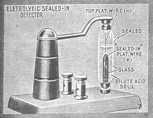 Another
form of electrolytic detector which will stand considerable rough usage is that known as
the Sealed-Point Electrolytic Detector. The commercial form of this instrument, as
here illustrated, is known as the Radioson, Fig. 7. The operation is the same as in
the bare-point electrolytic type of detector and a battery of two dry cells is used with
it, together with a pair of high resistance telephone receivers and having the battery
potential preferably regulated by means of a high resistance potentiometer. Another
form of electrolytic detector which will stand considerable rough usage is that known as
the Sealed-Point Electrolytic Detector. The commercial form of this instrument, as
here illustrated, is known as the Radioson, Fig. 7. The operation is the same as in
the bare-point electrolytic type of detector and a battery of two dry cells is used with
it, together with a pair of high resistance telephone receivers and having the battery
potential preferably regulated by means of a high resistance potentiometer.
ĀĀĀĀThe advantage of this type of electrolytic detector is that the
acid is sealed in, consequently does not spill or evaporate.
Ā
Ā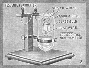
A detector of novel design and termed by Professor Fessenden, its inventor, a Barretter,
is shown at Fig. 8. This works on the heat or thermal principle. An extremely fine
platinum wire, about .003 inch in diameter, was first embedded in the middle of a silver
wire having a diameter of about one-tenth inch. This compound wire was then drawn until
the silver wire had a diameter of about .002 inch; as the platinum wire within it was
reduced in the same ratio, it would be drawn down to a final diameter of .00006 inch. As
shown in the illustration (Fig. 8), a short piece of this extremely fine platinum wire is
supported on two heavier silver wires, and the leads are taken out thru the outer glass
bulb for the purpose of connection in the radio receiving circuit. The tip of the fine
platinum wire loop had previously to be immersed in acid to dissolve away the silver
before the whole device was finally sealed up and the air exhausted from the containing
bulb.
When an oscillating electric current flows thru the extremely fine
platinum wire loop, it becomes heated and rapidly increases its electrical resistance. A
number of these Barretters were usually arranged in parallel and shunted by a
telephone receiver joined in series with a source of current, such as a single dry cell.
Hence, any variation of resistance of the barretter loops due to the heat produced by the
Hertzian wave currents, would be manifested in the telephone receivers owing to the change
in the amount of battery current past thru the circuit.
Ā
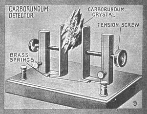 The Carborundum
Detector, discovered by General H.ĀH.ĀC. Dunwoody, U.S.A., (Fig. 9) involves
a marvelous characteristic possest by a number of minerals, viz., that of rectifying an
oscillating (alternating) current of practically any frequency. The carborundum detector
in its usual form comprises two rather stiff springs, adjustable as to pressure, between
which the carborundum (carbid of silicon) crystal (preferably an extremely jagged,
greenish specimen) is placed. A pair of high resistance telephones are shunted across the
detector and the incoming Hertzian wave oscillations, representing the dots and dashes of
the telegraphic code, are manifested as short and long signals in the phones owing to the
fact that the carborundum crystal will pass currents several hundred times better
in one direction than it will in the reverse direction. This action is enhanced by
mounting the crystal in a cup or clamp of large section, making the second electrode of
very small contact area. A steel needle has been used effectually as the small electrode
and in one commercial instrument the smaller electrode has been made of several steel
needles in contact with the carborundum. The Carborundum
Detector, discovered by General H.ĀH.ĀC. Dunwoody, U.S.A., (Fig. 9) involves
a marvelous characteristic possest by a number of minerals, viz., that of rectifying an
oscillating (alternating) current of practically any frequency. The carborundum detector
in its usual form comprises two rather stiff springs, adjustable as to pressure, between
which the carborundum (carbid of silicon) crystal (preferably an extremely jagged,
greenish specimen) is placed. A pair of high resistance telephones are shunted across the
detector and the incoming Hertzian wave oscillations, representing the dots and dashes of
the telegraphic code, are manifested as short and long signals in the phones owing to the
fact that the carborundum crystal will pass currents several hundred times better
in one direction than it will in the reverse direction. This action is enhanced by
mounting the crystal in a cup or clamp of large section, making the second electrode of
very small contact area. A steel needle has been used effectually as the small electrode
and in one commercial instrument the smaller electrode has been made of several steel
needles in contact with the carborundum.
Thus, the high frequency oscillations, or, rather, groups of
oscillations, are rectified and the summation of each train of waves reacts on the
'phones. Battery current usually intensifies the action of the carborundum detector but
its polarity must be watched, as also the potential applied. A potentiometer is best
employed to regulate the current applied to the detector.
Ā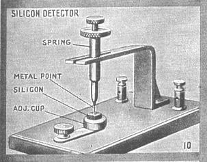
One of the best known radio detectors, and one that is now in extensive use, is the Silicon
Detector. This is illustrated at Fig. 10 and employs a piece of the mineral Silicon
embedded firmly in a brass cap. A solder or low heat alloy such as, Hugonium metal is best
used in mounting such minerals, so as not to injure their radio detecting properties or
sensitivity.
The Silicon detector is generally used without any battery and acts as
a rectifier, similarly to the carborundum detector. A pair of 2,000 ohm 'phones or higher
resistance ones, are shunted across the detector usually and owing to the rectifying
action already described, the incoming Hertzian wave currents are manifested as short and
long sounds in the 'phones.
Ā
Ā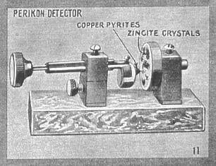
At Fig. 11 we have the Perikon Detector developed by G. W. Pickard. This detector
consists of two crystals--copper pyrites (Cu Fe S2) and zincite (zinc oxide
ZnO), held in firm contact against each other in the manner shown. The copper pyrite
crystal is mounted in a cup mounted on a spring-actuated rod provided with a suitable
knob, by which it can be swung in any direction. Zincite crystals are mounted in a large
cup containing several pockets, the mounting of both of the minerals being effected with a
low fusing solder, Wood's metal or Hugonium alloy. The action of the Perikon detector is
supposed to be based on the rectifying principle previously described; that is, it will
pass current in one direction but not in the other, and thus the incoming radio frequency
oscillating (alternating) currents in the aerial are rectified and caused to give a sound
in the high resistance 'phones connected to the detector. This detector is invariably used
with a battery of about two cells and the potential applied regulated by a potentiometer.
When using a battery the polarity of the current must be such that the positive wire is
connected to the copper pyrite crystal.
Ā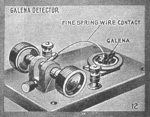
One of the most sensitive detectors, and one of the most popular with the radio amateur
because of its extreme simplicity, is the Galena Detector, Fig. 12. In this
instrument a piece of Galena (lead sulfide) is mounted in a brass cup by means of solder
or other low fusing alloy and a light phosphor bronze wire called a catwhisker
rests gently on the surface of the mineral. It is sometimes difficult to find sensitive
specimens of Galena, but it is a matter of record and a proven fact, that when a really
first-class specimen is obtained, it is practically second to no other detector, not even
excepting the Audion. Messages have seen received with a Galena detector and simple
equipment comprising a tuning coil, tin-foil and paper condenser and a single, high
resistance telephone receiver over a distance of 2,500 miles, when the transmitting
station was rated at only 5 K.W.
The Galena detector is practically never used with a battery and acts on the rectifying
principle possest by the minerals already discust.
Ā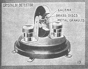 The Crystaloi
Detector (Fig. 13) is a very novel instrument and comparatively young as detectors go.
The detector does not require a battery and has a sensitivity on par with the average run
of mineral detectors. It comprises a hollow drum, or rather disk, as shown in the
illustration. This is supported between two vertical spring clips so that the drum may be
rotated on its axis until the maximum sensitivity is attained. Practically all mineral
detectors and also the Crystaloi are adjusted to maximum sensitivity by a "buzzer
test." An ordinary buzzer and battery, together with a key or push button, completes
this important piece of apparatus, and a single wire from the contact screw in front of
the buzzer armature is connected to the detector circuit or aerial circuit The Crystaloi
Detector (Fig. 13) is a very novel instrument and comparatively young as detectors go.
The detector does not require a battery and has a sensitivity on par with the average run
of mineral detectors. It comprises a hollow drum, or rather disk, as shown in the
illustration. This is supported between two vertical spring clips so that the drum may be
rotated on its axis until the maximum sensitivity is attained. Practically all mineral
detectors and also the Crystaloi are adjusted to maximum sensitivity by a "buzzer
test." An ordinary buzzer and battery, together with a key or push button, completes
this important piece of apparatus, and a single wire from the contact screw in front of
the buzzer armature is connected to the detector circuit or aerial circuit
The Crystaloi detector has two metal discs or plugs inserted in either
side of the hard rubber revoluble drum, one of which contains a small piece of sensitive
mineral. The space between the two metal disks is partially filled with a special mixture
of certain light metallic filings. When adjusting this detector, the revoluble drum is
moved a little at a time until the metal filings take up their proper position, making
contact between the plain metal disk on one side and the sensitive mineral on the other.
This action is quickly brought to a maximum by the application of the buzzer test current
thru an inductance of several turns of' wire. A pair of high resistance 'phones should be
used with this detector. Contrary to other mineral detectors, where only one
"catwhisker" contact wire is used, the Crystaloi uses the many contacting points
of the filings.
Ā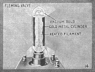
The Fleming Valve Detector of Hertzian oscillations (Fig. 14) is based upon the
principle that if we have a hot or incandescent electrode, and also a cold electrode, both
mounted within an evacuated glass chamber, a rectifying action will be created, i.e., that
negative electrical charges, such as those from a battery of 30 to 40 volts or even less,
can pass from the hot filament to the cold electrode but not vice versa. In the Fleming
Valve, the cold electrode takes the form of a metal cylinder surrounding the incandescent
filament. This arrangement acts as an electrical valve for oscillating or alternating
currents of any frequency. The space between the cold cylinder and the hot filament is
therefore said to possess unilateral conductivity. The Fleming Valve possesses a fairly
high sensitivity; it is used with a pair of high resistance head 'phones, a suitable
battery and auxiliary regulating apparatus. The wireless receiving phenomenon occurring
will be evident from the foregoing and is in a sense of a rectifying nature similar to
that possest by the mineral detectors.
Ā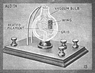
The Audion Detector (Fig. 15) employs three distinct electrodes as shown, viz., a
filament--a grid--and a wing or plate. The grid, composed of a wire member as indicated,
is p laced between the filament and wing. The oscillations when they pass thru the Audion
detector are subjected to a similar action to that occurring in the Fleming Valve; that
is, they are rectified, but in so doing they are claimed to also effect a relay action
with respect to a high voltage battery of 40 to 50 volts potential, connected to a pair of
high resistance telephone receivers in the wing circuit. Thus, with the Audion it is seen
that, owing to the suggested relay action inherent in its operation, it is quite possible
and practical to have such an action occurring of considerable magnitude; that is, the
ratio, between the amount of energy passing in to the Audion from the antenna circuit, and
the amount of energy controlled by the relay or trigger action in the high voltage 'phone
circuit may be quite large. Several years ago, when the first radio transmission was being
tried out between Honolulu and San Francisco by the Federal Telegraph Company, it was
found that due to the extreme sensitivity and amplifying action of the Audion, the signals
could be copied several hours longer each morning than with any other detector; the
signals fading as dawn approached, owing to the supposed ionization of the upper
atmospheric strata by the sun's rays.
There was, for a number of years, a great controversy on between the de
Forest and the Marconi experts as to the validity of the Audion patents. This matter was
discust in the November 1916, and also in the December 1916, issues of this journal and
those interested had best read both of these excellent articles as well as a very
exhaustive article explaining the action of the Audion which appeared in the August 1916,
issue of THEĀ ELECTRICALĀ EXPERIMENTER.
One important early detector omitted from this review is the
"imperfect contact", which in one common form consisted of a carbon rod resting
lightly on metal. This was one of the first techniques that provided audio reception of
signals, and was used from about 1900 to 1905, until being supplanted by more sensitive
electrolytic and crystal detectors.
|